
- SITEMAP
- CONTACT US
- 8618267732328
News
Credibility ,the lifeblood of enterprise!
- Fittings
- Butt Welding Fittings
- Forged Fittings
- 180 Degree Elbows
- 90 Degree Elbows
- 60 Degree Elbows
- 45 Degree Elbows
- 30 Degree Elbows
- Equal Tee
- Reducing Tee
- Concentric Reducer
- Eccentric Reducer
- Lap Joint Stub End
- Outlets
- Cap
- Bend
- Cross
- Coupling
- Stainless Steel Lateral Tee
- Bellows Expansion Joints
- Flexible Metal Hose
- Non-Standard/Custom Fittings
- Bleed & Flushing Rings
- Types of Flanges
- Anchor Flanges
- Blind Flanges
- Expander Flanges
- High Hub Flanges
- Lap Joint Flanges
- Long Weld Neck Flanges
- Nipoflanges
- Orifice Flanges
- Plate Flanges
- Ring Type Joint Flanges
- Reducing Flanges
- Slip On Flanges
- Socket Weld Flanges
- Spectacle Blind Flanges
- Square Flanges
- Spades & Ring Spacers
- Threaded Flanges
- Welding Neck Flanges


Failure analysis method and case of pipe sleeve
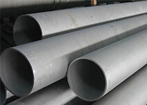
Recently contacted with a batch of long cylinder workpieces (see Fig. 1). During the acceptance of finished products, cracks were found on the surface of inner holes of four products. One of the most typical samples was cut and analyzed, as shown in Fig. 2 and Fig. 3.

Fig.1 Long barrel workpiece

Figure.2 Sectioning

Fig.3 Cracks and sampling positions found by MT after sectioning
Physical and chemical test and results
Chemical composition
The chemical composition of H1 sample was detected by direct reading spectrometer, and the results are shown in Table 1.
Table.1 results of spectral chemical composition analysis of H1 sample (mass fraction) (%)
Element |
C |
Si |
Mn |
P |
S |
Cr |
Mo |
Ni |
Cu |
Standard EN10083-3 |
0.38~0.45 |
≤0.40 |
0.60~0.90 |
≤0.025 |
≤0.025 |
0.90~1.20 |
0.15~0.30 |
— |
— |
Actual measurement |
0.40 |
0.22 |
0.74 |
0.010 |
— |
1.14 |
0.225 |
0.13 |
0.03 |
Hardness
Use Rockwell hardness tester to test the hardness value of H1 and B1 samples in the direction of wall thickness, and the results are shown in Table 2.
Table.2 Hardness distribution in the direction of wall thickness of H1 and B1 samples (HRC)
Hardness Sample |
1 |
2 |
3 |
4 |
5 |
Average value |
H1 |
29.0 |
25.8 |
26.3 |
27.7 |
28.0 |
27.4 |
B1 |
30.3 |
30.6 |
28.7 |
29.1 |
23.6 |
28.5 |
Microstructure
Grind and polish H1 specimen along n-PLANE and k-plane (see Fig. 4) (n-PLANE is the surface of inner hole, k-plane is the grinding and polishing surface along the direction of wall thickness), and observe in turn with microscope. The crack morphology of n-PLANE after polishing is as shown in Figure 5. Then, the polishing surface was eroded with 4% nitric acid alcohol solution, and the microstructure near the crack was observed, as shown in Fig. 6. The crack morphology and microstructure after erosion of surface k after polishing are shown in Fig. 7.

Figure.4 Grinding and polishing of H1 sample
 after polishing the inner hole surface of H1 sample")
Fig.5 Crack morphology (50x) after polishing the inner hole surface of H1 sample
")
Fig.6 Microstructure near inner hole surface crack of H1 sample (500X)

Figure.7 K-plane crack and microstructure of H1 specimen
The B1 specimen (see Figure 8) was polished and eroded along the n-PLANE and the k-plane respectively (n is the inner hole surface, K is the polishing surface along the wall thickness direction), and the crack morphology and microstructure nearby were observed under the microscope.

Fig.8 Grinding and polishing of B1 specimen along n-PLANE and k-plane respectively
There are many cracks on the inner hole surface of B1 sample. Under the microscope, its morphology is shown in Figure 9. Then, 4% nitric acid alcohol was used for erosion, and the microstructure near the surface crack of the inner hole was observed, as shown in Figure 10.

Figure.9 N-PLANE crack morphology of B1 sample (50x)

Fig.10 Microstructure near n-PLANE crack of B1 sample
After polishing in the direction of wall thickness of B1 sample, the crack morphology is as shown in Figure 11.

Figure.11 N-PLANE crack morphology of B1 sample
After etching the k-plane with 4% nitric acid alcohol solution, observe the microstructure near the crack, as shown in FIG. 12.

Fig.12 Microstructure near k-plane crack of B1 sample
Result analysis
From the above analysis results, it can be seen that the chemical composition of the raw material used for this part meets the requirements of 42CrMo4 in en 10083-3, and no element exceeding the standard is found. According to the hardness test results of the cut-off test block, there is no obvious gradient change in the hardness of the pipe sleeve along the thickness direction, which indicates that the workpiece has been hardened thoroughly and tempered fully during quenching.
According to the actual heat treatment process of the pipe sleeve, the actual heat treatment process curve is shown in Figure 13, and no abnormality is found in the production process.

Fig.13 Quenching and tempering curve of pipe sleeve
From the crack morphology observed after grinding, the crack tip on the inner hole surface and wall thickness direction of sample H1 and sample B1 is relatively sharp, and its propagation path is transgranular, which is a typical quenching crack. According to the microstructure after erosion, the microstructures near the cracks of the two samples are tempered sorbite, no massive ferrite and long strip ferrite are found, and no obvious oxide decarburization layer is found on both sides of the cracks. This shows that the cracks are formed in the process of heat treatment.
In fact, for the finished long tube parts, the wall thickness is 40mm (thin wall end) and 52mm (thick wall end), respectively. In general, the inner hole is relatively long, the inner diameter is small and the wall thickness belongs to 42CrMo4 steel, which can be fully quenched, and the structure stress is relatively large during quenching. At the same time, for the deep hole parts with small inner diameter, because the cooling speed of the inner surface is much smaller than that of the outer surface and the effect of residual thermal stress is small, the tensile stress on the inner surface is larger than that on the outer surface, and it is easy to form longitudinal cracks on the inner surface, or even multiple parallel cracks (see Figure 14).

Figure.14 Distribution and crack of quenching residual stress of deep hole parts
Conclusion and preventive measures
- (1) Through the body sampling analysis, it can be seen that the pipe sleeve crack belongs to a typical quenching crack, which is caused by the excessive internal stress of the workpiece during quenching, especially the excessive tensile stress on the surface of the inner hole.
- (2) In order to avoid this kind of cracks, measures can be taken to reduce quenching temperature, increase the speed and efficiency of quenching medium flowing along the inner hole, and increase the final cooling temperature, so as to reduce quenching stress and avoid workpiece cracking.
Source: China Pipe Sleeve Manufacturer - Yaang Pipe Industry Co., Limited (www.yaang.com)

Tel No:+86-18267732328 / Email:[email protected]
Address:Longwan District, Wenzhou, Zhejiang Province, China.
Copyright Notice © www.yaang.com Yaang Pipe Industry Co., Limited All rights reserved.
Yaang Pipe Industry Co., Ltd. is an international supplier of piping solutions for flange, butt welding fittings, socket welding fittings and threaded fittings. Our products are widely used in different industrial fields, including oil and gas, chemical industry, petrochemical industry, power plant, pulp and paper industry, environmental and water conservancy engineering, engineering projects, etc.
