- SITEMAP
- CONTACT US
- 8618267732328
News
Credibility ,the lifeblood of enterprise!
- Fittings
- Butt Welding Fittings
- Forged Fittings
- 180 Degree Elbows
- 90 Degree Elbows
- 60 Degree Elbows
- 45 Degree Elbows
- 30 Degree Elbows
- Equal Tee
- Reducing Tee
- Concentric Reducer
- Eccentric Reducer
- Lap Joint Stub End
- Outlets
- Cap
- Bend
- Cross
- Coupling
- Stainless Steel Lateral Tee
- Bellows Expansion Joints
- Flexible Metal Hose
- Non-Standard/Custom Fittings
- Bleed & Flushing Rings
- Types of Flanges
- Anchor Flanges
- Blind Flanges
- Expander Flanges
- High Hub Flanges
- Lap Joint Flanges
- Long Weld Neck Flanges
- Nipoflanges
- Orifice Flanges
- Plate Flanges
- Ring Type Joint Flanges
- Reducing Flanges
- Slip On Flanges
- Socket Weld Flanges
- Spectacle Blind Flanges
- Square Flanges
- Spades & Ring Spacers
- Threaded Flanges
- Welding Neck Flanges
Forging of deep hole forgings with intermediate flanges
In Automotive "half-shaft casing flange" and "steering knuckle shaft" deep hole long rod parts, in the traditional process, the deep hole in the rod is generally not forged out. Its machining allowance and release angle are large, not only a waste of raw materials, increased machining hours, and forging labor intensity large, low production efficiency. Because of the above technical difficulties, we designed a unique floating die holder and successfully forged deep holes with intermediate flange forgings.
Take the deep hole forgings provided by a foreign user as an example; the forging products are used on precision machine tools with speeds higher than 8000 r.min-1. The rough machining diagram is shown in Fig.1; the dimensions of deep hole parts are: outer diameter Φ79mm, inner diameter Φ62mm, through-hole length 210.5mm, middle flange outer diameter Φ154mm, flange thickness 18mm, the forging material is 45# steel, requiring normalization + high temperature tempering treatment, mechanical properties are required: tensile strength Rm ≥ 570MPa, elongation A ≥ 20%. The user cannot use cast steel or welded parts; forging forming is required. To this end, the design of deep hole forgings is shown in Figure 2. Thin-walled deep hole forgings usually use special hydraulic equipment, using a slower rate of positive or negative extrusion for production and processing. For the deep hole forgings with intermediate flange, as shown in Figure 2, another set of hydraulic equipment should be considered to press the upper and lower two separate forming dies when extruding deep holes to ensure the completion of the intermediate deep hole with flange extrusion and extrusion mandrel.
1. Process development
The forging equipment is a friction screw press and electric screw press, developed as shown in Figure 3 pre-forging partial forming, final forging using floating die seat hot extrusion deep hole forming forging process, which includes 2 work steps to meet the customer's expectations.
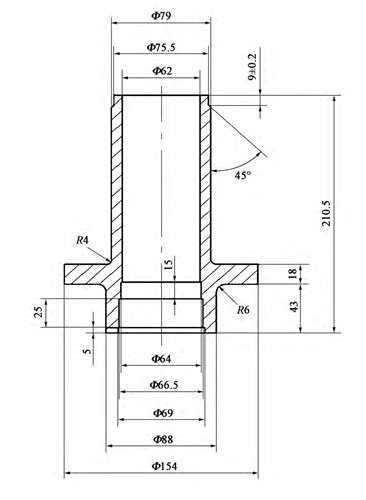
Fig.1 Rough machining of deep hole forgings
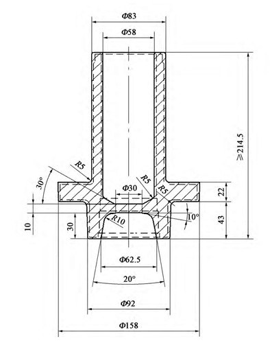
Fig.2 Deep hole forging
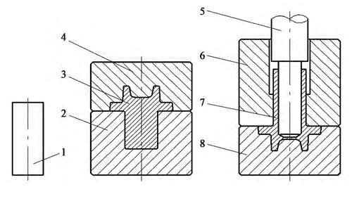
1. forging billet; 2. pre-forging lower die; 3. pre-forging part; 4. pre-forging upper die; 5. extrusion mandrel; 6. final forging upper die; 7. deep hole forging part; 8. final forging lower die
1.1 Step 1: Pre-forging partial forming
To make the next step extrusion deep hole can be effectively positioned, consider the shape of the lower part of the deep hole forging shown in Figure 2 forging in place. The key to pre-forging partial forming is that the outer circle of the flange cannot have burrs after forging. Otherwise, the final forging will squeeze into the body of the forging, causing the forging to fold and scrap. As the metal flow at the flange varies with the shape of the cavity, consider the design of a suitable depth of the lower cavity for reasonable material distribution and control the outside diameter of the flange when pre-forging partial forming is smaller than the outside diameter of the flange of deep hole forgings.In the next step of deep hole extrusion, it is necessary to ensure that the upper die is first set into the pre-forged semi-finished products, pressing the flange. For this reason, the diameter of the bottom cavity of the pre-forging die is Φ82mm, the diameter of the hole is Φ83mm, and the diameter of the billet is Φ80mm to ensure the effective positioning of the billet after it is put into the die. Before pre-forging, the oxide removal equipment removes the billet surface oxide, and then it is put into the die directly for pre-forging and partial forming. Since the lower cavity is deep and the die-pulling slope is only 0.5°, while the upper cavity is shallow and the die pulling slope is 10°, the pre-forged semi-finished products will be left in the lower die after forming; the ejector is needed to take out the pre-forged semi-finished products.
1.2 Step 2: Final forging and extrusion of deep hole forming
As shown in Figure 4, the pre-forged parts in the first step will be put into the final forging lower die, and the final forging upper die will be installed on the lower floating die plate before the deep hole extrusion, driven by the spring force, first close with the final forging lower die. The upper floating die plate driven by the press slider continues to press down, forcing the pressure spring to compress, increasing the spring force gradually will be tightened on the upper and lower final forging die. At the same time, the extrusion mandrel gradually squeezes down until the upper and lower floating die plate. When the plates are completely together, the deep hole with intermediate flange forging back extrusion forming. When the ram of the press rises, the upper and lower floating die plates are separated under the action of the pressure spring, and the extrusion mandrel is taken off the deep hole forging. At this time, the circulating cooling and lubricating system around the extrusion mandrel is started, which cools and lubricates the extrusion mandrel simultaneously, making the deep hole forging cool and free from the final forging upper die.
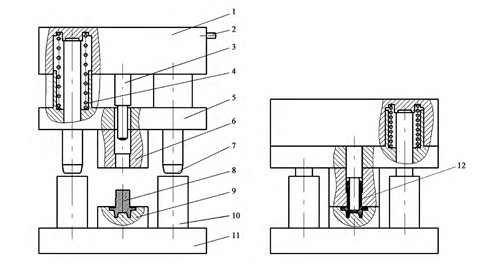
1. upper floating die plate; 2. cooling water inlet; 3. extrusion mandrel; 4. pressure spring; 5. lower floating die plate; 6. final forging upper die; 7. guide pillar; 8. pre-forged parts; 9. final forging lower die; 10. guide sleeve; 11. lower die plate; 12. deep hole forging;
The deep hole extrusion deformation mode for reverse extrusion cup-shaped parts, extrusion end, deep hole section deformation degree ε ≈ 49% (ε = d2 / D2 x 100%, where d is extruded deep hole internal diameter, D is the outer diameter of deep hole parts), extrusion ratio G = 1.95 (G = D2 / (D2 - d2)).
1.3 Spring force and deformation control
Because the size of the spring force and the distance between the upper and lower floating die plate is inversely proportional to the extrusion mandrel contact with the pre-forging billet extrusion, the compression force between the upper and lower final forging die is not enough to resist the metal deformation flow resistance of deep hole forgings, therefore, in the pre-forging local forming, the flange outside diameter and thickness dimensions are required than the final forging a certain value of small, so that the initial extrusion of the deep hole at the same time, part of the metal flow to the flange Part, control the deep hole and flange size in line with the requirements, and no flying edge.Suppose the spring compression force is too small and cannot effectively compress the upper and lower final forging dies. In that case, the extrusion of metal will flow into the flange part, resulting in flange thickness size, extrusion of flying edge, deep hole extrusion depth not enough, and other problems; at the same time, at the end of the extrusion of deep hole forgings and extrusion mandrel cannot be extruded and hold the extrusion mandrel phenomenon. Therefore, the design of the spring is very important, related to the success or failure of the forging process of deep hole forgings with intermediate flange.
As shown in Figure 2, the extrusion depth of deep hole forgings ≥ 174.5 mm; that is, the compressible deformation of the spring after deducting the pre-compression distance must be ≥ 174.5 mm, the actual take 200 mm. According to the structure and space position of the floating die frame, the choice of four class II cylindrical spiral compression springs, material 60Si2Mn A steel, the specific parameters are: wire diameter d = 25 mm, diameter D2 = 130mm, pitch t=43.1mm, effective number of turns n=14.5, working load Pn=2300kg, ultimate load Pj=2900kg (equivalent to the working load of class III spring Pn), single turn stiffness P'd=177.799 kg.mm-1, minimum working load P1=300kg (the upper floating die plate weighs about 1000kg, and the single spring load bearing 250kg). Spring stiffness P'=P'd/n=12.3 kg.mm-1, spring compression deformation under the ultimate load Fj=Pj/P'=235.8mm, spring compression deformation under the minimum working load F1=P1/P'=24.4mm, Fj-F1=211.4mm>200mm, to meet the required spring compression deformation.
2. Quality inspection of forgings
2.1 Appearance and dimensional inspection
The forged deep hole forgings are inspected, and the external dimensions and the dimensions after rough machining are to the requirements of the drawings. Fluorescent magnetic particle inspection did not find forging surface folding, cracking, or other defects. The physical anatomy diagram is shown in Figure 5.2.2 Macrostructure inspection
The fiber flow line of deep hole forgings after dissection and corrosion is shown in Figure 6. The fiber flow line is continuous and smooth, per the design requirements.2.3 Microstructure inspection
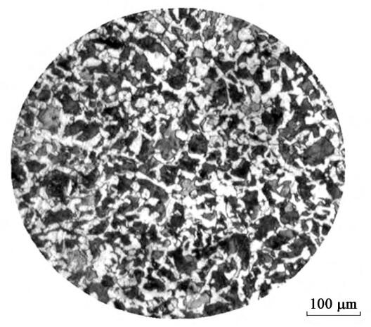
According to the user's requirements, the deep hole forgings need to be normalized + tempering treatment; the grain size after heat treatment is shown in Figure 7, reaching about grade 7, to meet the use requirements.
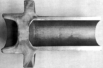
Figure.5 Deep hole forgings physical cross-section
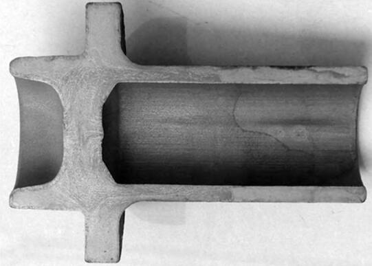
Figure.6 Deep hole forging fiber flow line diagram
2.4 Mechanical performance test
Users require deep hole forgings products with tensile strength Rm ≥ 570MPa, elongation A ≥ 20%. In the deep hole wall thickness, part of the sample made of test bar, tensile test, measured mechanical properties parameters data is: tensile strength Rm = 756MPa, yield strength ReL = 426MPa, elongation A = 22.5%, section shrinkage Z = 39%, are higher than the user requirements.3. Conclusion
The trial production results show that the forging process, dies, and tooling design of the deep hole with intermediate flange forgings are reasonable and achieve the expected purpose; the parameters of the forgings are in line with the technical requirements of the user drawings.The original forgings used by the user are blind hole forgings at both ends, the shape needs not less than a 3° to die slope, and the deep hole is achieved by cutting. The deep hole forgings provided by our company can save about 5-6kg of material per piece and save the time and cost of post-processing, which customers highly appreciate.
Author: Jing Yifeng
Source: China Forgings Manufacturer - Yaang Pipe Industry Co., Limited (www.yaang.com)

Tel No:+86-18267732328 / Email:[email protected]
Address:Longwan District, Wenzhou, Zhejiang Province, China.
Copyright Notice © www.yaang.com Yaang Pipe Industry Co., Limited All rights reserved.
Yaang Pipe Industry Co., Ltd. is an international supplier of piping solutions for flange, butt welding fittings, socket welding fittings and threaded fittings. Our products are widely used in different industrial fields, including oil and gas, chemical industry, petrochemical industry, power plant, pulp and paper industry, environmental and water conservancy engineering, engineering projects, etc.

