
- SITEMAP
- CONTACT US
- 8618267732328
News
Credibility ,the lifeblood of enterprise!
- Fittings
- Butt Welding Fittings
- Forged Fittings
- 180 Degree Elbows
- 90 Degree Elbows
- 60 Degree Elbows
- 45 Degree Elbows
- 30 Degree Elbows
- Equal Tee
- Reducing Tee
- Concentric Reducer
- Eccentric Reducer
- Lap Joint Stub End
- Outlets
- Cap
- Bend
- Cross
- Coupling
- Stainless Steel Lateral Tee
- Bellows Expansion Joints
- Flexible Metal Hose
- Non-Standard/Custom Fittings
- Bleed & Flushing Rings
- Types of Flanges
- Anchor Flanges
- Blind Flanges
- Expander Flanges
- High Hub Flanges
- Lap Joint Flanges
- Long Weld Neck Flanges
- Nipoflanges
- Orifice Flanges
- Plate Flanges
- Ring Type Joint Flanges
- Reducing Flanges
- Slip On Flanges
- Socket Weld Flanges
- Spectacle Blind Flanges
- Square Flanges
- Spades & Ring Spacers
- Threaded Flanges
- Welding Neck Flanges


What is a breather valve?
What is a breather valve?
Breather valve is a kind of valve which can not only keep the tank space isolated from the atmosphere within a certain pressure range, but also connect with the atmosphere (breathing) when the pressure range is higher or lower. Its function is to prevent the tank from being damaged due to overpressure or vacuum, and to reduce the evaporation loss of the storage liquid. It is mainly composed of valve seat, valve cover, protective cover and two groups of opening and closing devices controlled by vacuum and pressure. The opening and closing device includes valve disc, guide rod, spring, spring seat and sealing ring. When the pressure in the tank reaches the rated exhaled positive pressure, the pressure valve flap opens and the steam in the tank is discharged; when the vacuum degree in the tank reaches the rated suction negative pressure, the vacuum valve flap opens and the air enters.
Structure characteristics of breather valve
- The breather valve is made of cast iron, cast steel, aluminum alloy and stainless steel with good corrosion resistance.
- The valve disc and seal ring are made of stainless steel tetrafluoroethylene.
- The breather valve has good low temperature resistance and antifreeze performance.
- The breather valve is a ventilation device installed on the fixed roof tank to reduce the evaporation loss of oil and control the pressure of the tank.
- The breather valve has the advantages of large ventilation, small leakage, corrosion resistance and good antifreeze performance. It can automatically adjust the pressure inside and outside the oil tank.
Function of breather valve
- 1. When the pressure of the medium in the tank is within the control operating pressure range of the breather valve, the breather valve does not work to maintain the tightness of the oil tank;
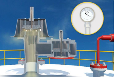
- 2. When the medium is added to the tank to increase the pressure in the upper gas space of the tank and reach the positive operating pressure of the breather valve, the pressure valve is opened and the gas escapes from the breather valve exhalation outlet, so that the pressure in the tank does not continue increase; as shown in the figure below:
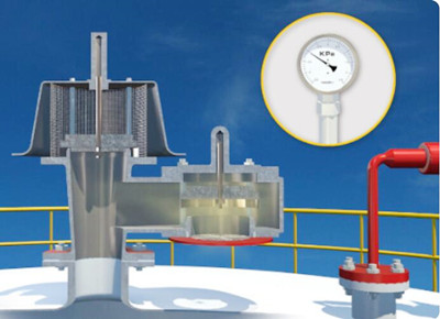
- 3. The atmosphere outside the tank will open the negative pressure valve disc of the breather valve and suck in air; as shown in the figure below:
- (1) When the storage tank outputs materials, the breather valve begins to suck air or nitrogen into the tank.
- (2) When the material is filled into the tank, the breather valve starts to exhale the gas from the tank to the outside.
- (3) Due to climate change and other reasons, the vapor pressure of materials in the tank increases or decreases, and the breather valve exhales steam or inhales air or nitrogen (usually called thermal effect).
- (4) In case of fire, the evaporation of liquid in the tank increases sharply due to the heat of exhaled gas, and the breather valve begins to exhale out of the tank, so as to avoid the damage of the tank due to overpressure.
- (5) In other working conditions, such as the pressurized transportation of volatile liquid, chemical reaction of internal and external heat transfer devices, misoperation, etc., the breather valve will exhale or inhale accordingly, so as to avoid damage to the storage tank due to overpressure or ultra vacuum.
Working principle of breather valve

Common standards for Breather valves
- SY/T 0511.1-2010 "Petroleum Storage Tank Accessories Part 1: Breather valve"
- TB/T 3319-2013 "Breathing safety valve for railway tank car"
- QC/T 1064-2017 "Tank Vehicle Breather valve for Road Transport of Flammable Liquid and Dangerous Goods"
- DIN EN 14595-2016 "Dangerous Goods Transport Tank, Tank Operating Device Pressure and Vacuum Breather valve"
Classification of breather valve
Tight breather valve
Packed breather valve
Self-sealing breather valve
Oil-sealed breather valve
Classified by material
Classified by working principle
Installation of Breather valve
- 1. Remove the packaging, it is very important to read the product description.
- 2. When hoisting the breather valve, appropriate lifting tools should be used to avoid damage to the protective cap of the breather valve disc.
- 3. Check the coaxiality and verticality of the pipe flange on the tank or water tank, which is essential for the normal use of the pressure and vacuum relief valve (Breather valve).
- 4. Check the waterline surface of the pipe flange on the tank or water tank. It must be clean, free of scratches, corrosion, tool marks, and flat.
- 5. Remove the flange port protection cover and other packing materials.
- 6. Check the gasket; make sure the material is suitable for the application.
- 7. Use the bolt circle to center the washer.

Installation points of Breather valve
- (1) The Breather valve should be installed at the highest point on the top of the tank. Theoretically speaking, from the viewpoint of reducing evaporation loss and other exhaust gas, the breather valve should be installed at the highest point of the gas phase space of the tank in order to smoothly provide the most direct and largest passage to the breather valve.
- (2) When the volume of the storage tank is large or the storage tank is more important, in order to prevent the risk of overpressure or negative pressure in the storage tank due to failure of a single Breather valve, two Breather valves can be installed at this time. In order to avoid two Breather valves operating at the same time and increasing the probability of failure, during process design, the suction and discharge pressure gradients of the two Breather valves are usually designed. Normally, the next one works and the other is standby.
- (3) If the breather volume is too large and the breather volume of a single Breather valve cannot meet the requirements, more than two Breather valves can be set. When installing two Breather valves, their distance from the center of the tank top should be equal, that is, they are arranged symmetrically on the tank top.
- (4) If the breather valve is installed on a nitrogen-sealed storage tank, the position of the nitrogen gas supply pipe must be far away from the breather valve interface and inserted into the storage tank from the top of the tank for about 200mm, so that the nitrogen is not directly discharged after entering the tank. Nitrogen sealing effect.
- (5) If there is a flame arrestor in the breather valve, the influence of the pressure drop of the flame arrestor on the discharge pressure of the breather valve must be considered to avoid overpressure in the storage tank.
- (6) When the average temperature of the coldest month in the tank building area is lower than or equal to 0, the breather valve must have anti-freezing measures to prevent freezing or blocking of the breather valve valve disc, resulting in poor exhaust or insufficient air supply of the storage tank , Which leads to overpressure drum or low pressure deflated tank.
Breathing discharge calculation of breather valve
- LB=0.191×M(P/(100910-P))^0.68×D^1.73×H^0.51×△T^0.45×FP×C×KC
- LB-respiratory discharge volume of fixed top tank (Kg/a);
- M-the molecular weight of the vapor in the tank;
- P-In a large amount of liquid state, the true vapor pressure (Pa);
- D-The diameter of the tank (m);
- H-average vapor space height (m);
- △T- the average temperature difference within a day (℃);
- FP-coating factor (dimensionless), the value is between 1 and 1.5 according to the paint condition;
- C-Adjustment factor for small diameter tanks (dimensionless); For tanks with a diameter between 0-9m, C=1-0.0123(D-9)^2; C=1 for tanks with a diameter greater than 9m;
- KC-product factor (Petroleum crude oil KC is 0.65, other organic liquids are 1.0).
Working discharge calculation of Breather valve
- LW=4.188×10^-7×M×P×KN×KC
- LW-Work loss of fixed roof tank (Kg/m3 input);
- KN-Turnover factor (dimensionless), the value is determined by the number of annual turnover (K).
- K<=36,KN=1
- 36<K<=220,KN=11.467×K^-0.7026
- K>220, KN=0.26
Pressure test of Breather valve
Maintenance of Breather valve
How to choose the right breather valve
- 1. For the requirements of the installation location and temperature range, such as cold areas, all-weather Breather valves should be used, and pipeline breather valves should be used for installation in pipelines.
- 2. The control pressure of the mechanical Breather valve should be compatible with the relevant pressure bearing capacity.
- 3. The specifications (flange diameter) of the mechanical Breather valve should meet the requirements of the maximum flow rate of breather gas in and out of the oil tank.
- 4. Consider the exhalation volume caused by the increase in the evaporation of liquid in the tube caused by the heating of the tank during a fire.
- 5. Under the influence of climate, the increase of vapor pressure in the tank decreases, resulting in the thermal effect of breather.
- 6. Anti-freeze Breather valve should be selected for selection in northern cold regions.
- 7. The maximum amount of liquid in and out of the tank.
Confirm the minimum pressure of the vessel design and the maximum allowable pressure of the vessel, that is, the determination of negative pressure and positive pressure, and the operating pressure range.
Source: China Valves Manufacturer – Yaang Pipe Industry Co., Limited (www.yaang.com)

Tel No:+86-18267732328 / Email:[email protected]
Address:Longwan District, Wenzhou, Zhejiang Province, China.
Copyright Notice © www.yaang.com Yaang Pipe Industry Co., Limited All rights reserved.
Yaang Pipe Industry Co., Ltd. is an international supplier of piping solutions for flange, butt welding fittings, socket welding fittings and threaded fittings. Our products are widely used in different industrial fields, including oil and gas, chemical industry, petrochemical industry, power plant, pulp and paper industry, environmental and water conservancy engineering, engineering projects, etc.
